Basics of Quantum Computing Hardware
Quantum computing demonstrates immense computational potential in specific problems compared to classical computers. However, its hardware faces challenges such as difficulty in control and short operation times. Quantum computing hardware revolves around quantum bits (qubits) as core components, supplemented by driving components to manipulate qubit states and readout components to measure them. Furthermore, due to qubits' susceptibility to external interference, calibration/adjustment components and quantum error correction components are also necessary. In summary, they can be categorized as follows:
- Qubits
- Driving components
- Readout components
- Calibration components
- Error correction components
In fact, current memory systems also include similar hardware divisions, but in quantum computing, these components need to be considered holistically. More specifically, due to interactions between different components, when quantum physics is employed to describe the entire quantum circuit using its Hamiltonian (or Schrödinger equation), the interactions will "modify" the properties of qubits. On one hand, these modifications enable the operation and measurement of qubit information; on the other hand, they cause deviations from ideal states, leading to errors.
This article focuses on superconducting quantum circuits, with the components in quantum circuits categorized as follows (from two perspectives):
| From a functional perspective |
1. Qubits (Data storage) 2. Driving components: Coupling circuits or LC resonators (for computation) 3. Readout components: LC resonators and feedlines 4. Calibration components: Flux lines (to adjust qubit frequencies) 5. Error correction components: Qubits (used for error correction) |
|---|---|
| From a component perspective |
1. LC Circuits a. LC resonators (linear LC circuits): Used for reading qubit states (readout resonators) and sometimes for indirect coupling between qubits b. Qubits (nonlinear LC circuits): Partly for data storage, partly for error correction 2. feedlines: Delivering and receiving external signals 3. Coupling components: a. Operating and changing qubit states b. Direct coupling between qubits c. Exchanging signals between external sources and components 4. Flux lines: Adjusting qubit frequencies to ensure qubits operate at specific frequencies |
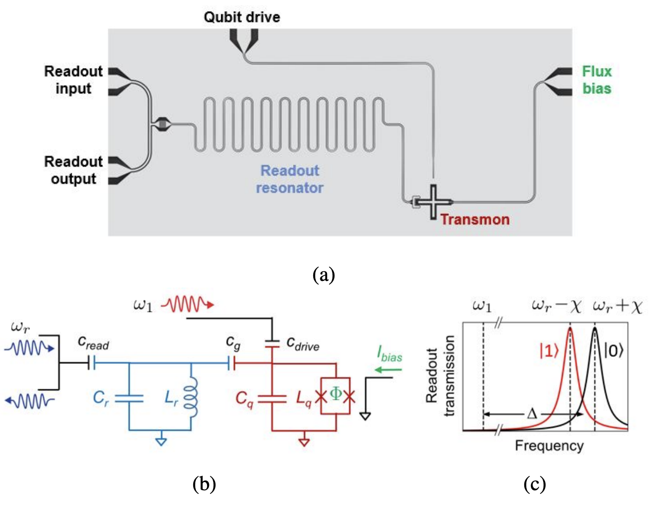
▲ Let's first take a look at the layout of a single qubit. (a) A microscope view of the circuit, (b) the corresponding circuit diagram. This diagram includes a qubit (red transmon), a readout resonator (light blue), and two feedlines separately driving the qubit and the readout resonator. Components are coupled via capacitors. Additionally, a flux line near the qubit generates a magnetic field to adjust the operational frequency of the transmon. (c) The readout resonator, coupled to the qubit, shows spectral shifts depending on whether the qubit is in state \(|0\rangle\) or \(|1\rangle\). This spectral shift allows determination of the qubit state.
arxiv.org/pdf/2106.11352
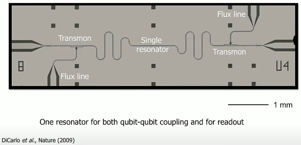
▲ This image shows two qubits (transmons) coupled through a resonator (indirect coupling). Note the text below indicating that the resonator also functions as a coupler between the two qubits.
doi.org/10.1038/nature08121
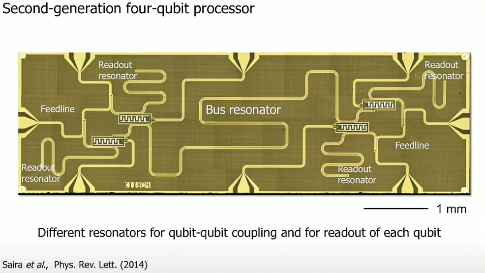
▲ This image shows four qubits connected via a bus resonator. Each qubit is directly connected to flux lines, and there are readout feedlines on the top-\mathcal{L}eft and bottom-right. Each feedline is connected to two readout resonators, coupling with two qubits simultaneously.
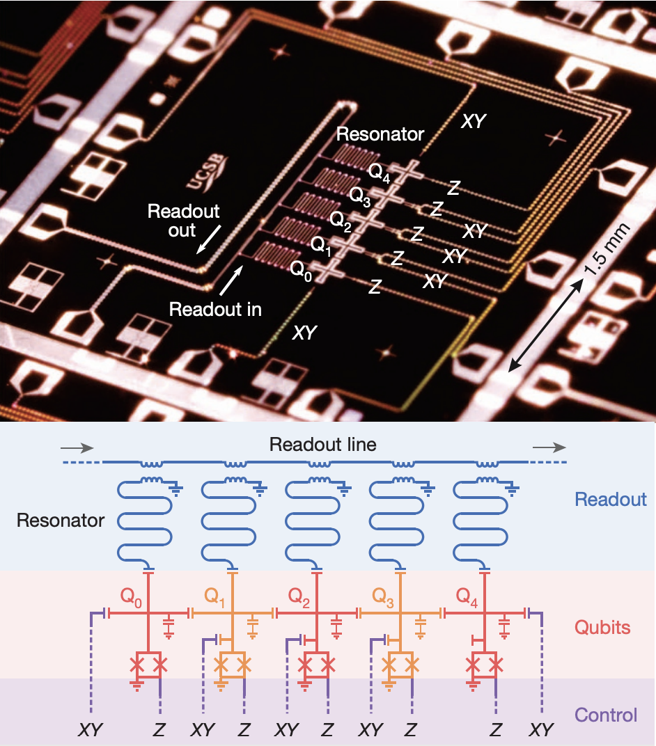
▲ This is a schematic of a 5-qubit layout. Here, Z represents flux lines, and XY represents drive lines. The five qubits are directly coupled via capacitors. Each qubit has its own readout resonator, which merges (inductively coupled) into the readout line.
doi.org/10.1038/nature13171
Towards Multi-Qubit Modules


▲ To achieve quantum computation, many qubits must be operated simultaneously. Due to error correction requirements, additional qubits are needed for this purpose. Above is an experimental 17-qubit quantum chip, arranged in a surface code configuration for quantum error correction. The qubits are shown in pink and red circles as data qubits, and light blue and green as check qubits. Each qubit connects to seven lines (nicknamed Starmon), including four for qubit coupling, one flux line, one drive line, and one readout resonator. The readout resonators are merged into three feedlines.
https://arxiv.org/pdf/1612.08208
Originally written in Chinese by the author, these articles are translated into English to invite cross-language resonance.
 Peir-Ru Wang