Decoherence-Time Drift
Why Do Superconducting Quantum Computers Require Frequent Calibration?
A superconducting quantum computer is not a machine that can be calibrated once and then remain stable for a long time. The qubit frequency, energy relaxation time \(T_1\), phase decoherence time \(T_2\), readout response, and two-qubit gate parameters can all drift over time. As a result, real quantum processors must be calibrated repeatedly during operation.
In superconducting quantum computers, calibration usually involves the qubit frequency, microwave pulse amplitude, pulse duration, phase, readout threshold, coupler bias, and two-qubit gate conditions. All of these parameters depend on the qubit’s instantaneous spectrum and decoherence environment. Quantum hardware is intrinsically time-dependent. Superconducting qubits are artificial atoms fabricated by lithographic processes, and they can couple to defects on material surfaces, oxide layers inside Josephson junctions, nonequilibrium quasiparticle events, package modes, background radiation, and noise in control lines. These environmental degrees of freedom modify the qubit’s decoherence channels, meaning that the optimal parameters measured yesterday may no longer be optimal today.
If the qubit frequency drifts, a previously accurate \(\pi\) pulse may no longer perform a perfect bit flip. If \(T_1\) decreases, the qubit has a higher probability of relaxing from the excited state back to the ground state before the gate operation or readout is completed. If the response of the readout resonator changes, the previously calibrated classification threshold may lead to a higher readout error rate. Therefore, superconducting quantum computers require frequent calibration because their operating points and error models change over time.
Ideally, a qubit should evolve only according to the control pulses that we intentionally design and apply. In practice, however, it can leak energy or phase information into the environment through specific physical pathways. These pathways of information leakage are called decoherence channels.
|
Energy Relaxation Channels |
Phase Decoherence Channels |
|---|---|
|
|
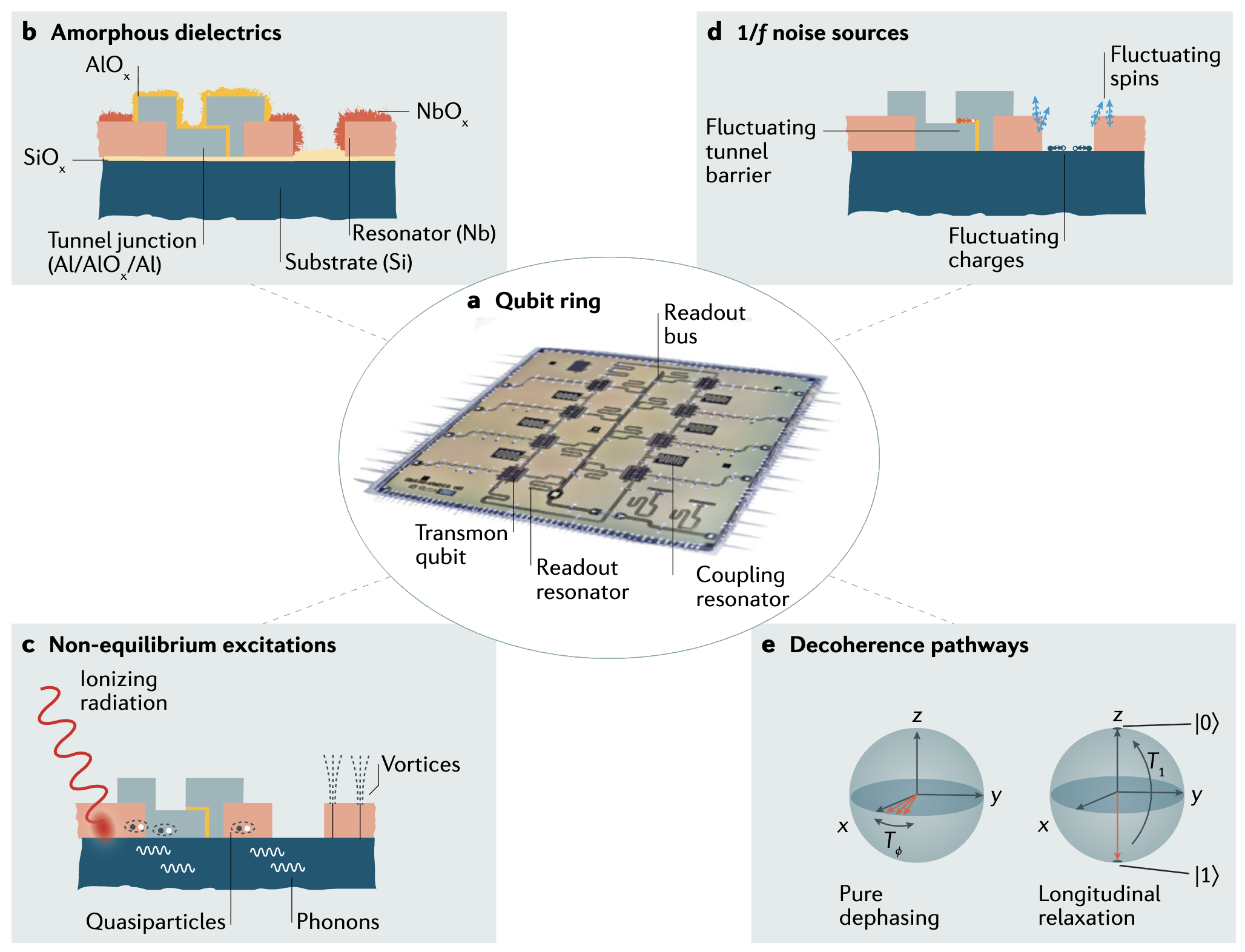
▲ Schematic illustration of decoherence sources.
a. Optical image of a qubit chip consisting of eight transmon qubits. These qubits use \(Al/AlO_x/Al\) Josephson junctions (JJs), surrounded by niobium (\(Nb\)) microwave circuits. The qubits are coupled to neighboring qubits through resonators, and each qubit is equipped with its own resonator for quantum-state readout. The readout signals can be multiplexed and transmitted to a shared bus.
b. Decoherence may originate from defect layers or amorphous layers at surfaces and interfaces, which introduce parasitic dielectric loss.
c. Nonequilibrium excitations in superconducting films and substrates may be triggered by ionizing radiation, high-energy particles, or residual magnetic fields. These noise sources can generate quasiparticles, thermal phonons, and magnetic flux vortices.
d. Microscopic charge and spin defects can generate \(1/f\) fluctuation noise, exposing the qubit circuit to time-dependent electric or magnetic bias fields. If such defects exist inside the tunneling barrier, they may also change the inductance of the Josephson junction.
e. Pure dephasing \(T_\phi\) originates from environmental noise that perturbs the energy levels of the qubit, whereas longitudinal relaxation \(T_1\) occurs when environmental perturbations exchange energy with the qubit, causing decay.
Ref: 10.1038/s41578-021-00370-4
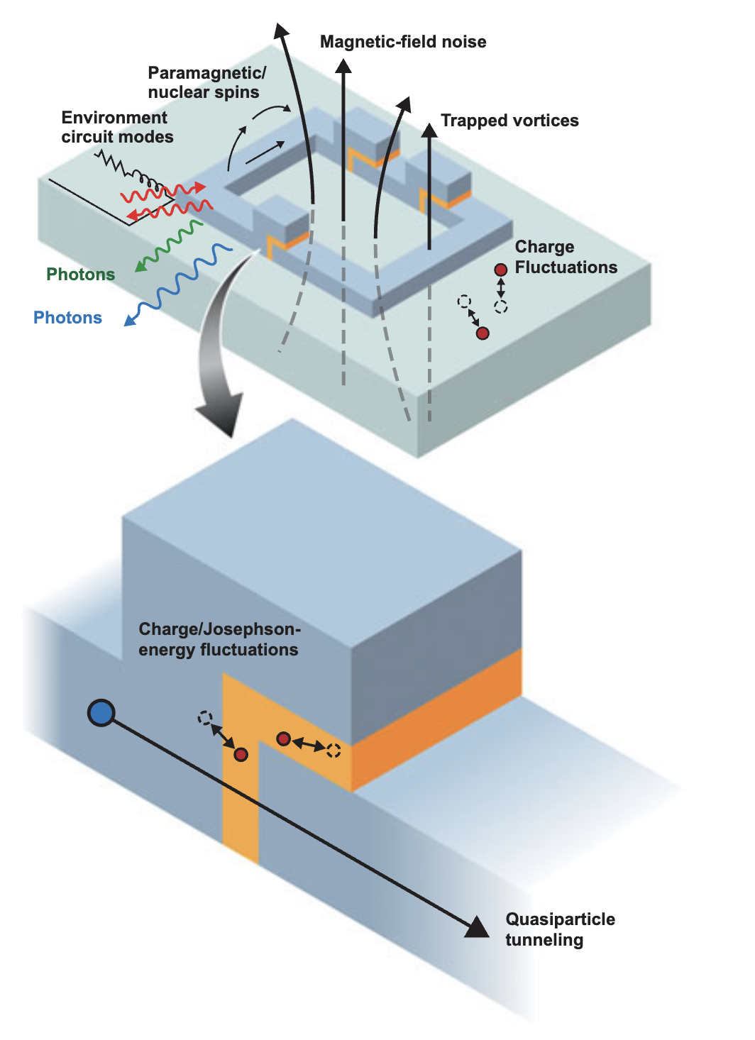
▲ Schematic illustration of decoherence sources, including noise from control circuitry, nuclear-spin perturbations in materials, thermal phonons, charge fluctuations, electromagnetic interference, bias-field fluctuations, and trapped magnetic vortices. Near the tunneling barrier, quasiparticle tunneling events can strongly disturb the properties of the qubit.
Ref: 10.1557/mrs.2013.229
Material Surfaces and Josephson Junctions Are Major Sources of Decoherence Noise
The electric field of a superconducting qubit is distributed around metal edges, substrate surfaces, oxide tunneling barriers, and packaging structures. If defects or contaminants are present in these regions, the qubit can couple to them. This is especially important near the Josephson junction, where the aluminum oxide tunneling barrier is extremely thin. Local atomic arrangements, impurities, and defects can all influence the critical current and microwave loss.
Surface-adsorbed molecules, residual photoresist, oxides, contaminants, and structural defects may all form fluctuating electric dipoles. State switching in these microscopic degrees of freedom can cause charge noise, frequency noise, or fluctuations in \(T_1\). From the perspective of calibration, this means that every qubit may have its own drift characteristics. Different chips, different fabrication batches, and even different locations on the same chip can exhibit different levels of stability.
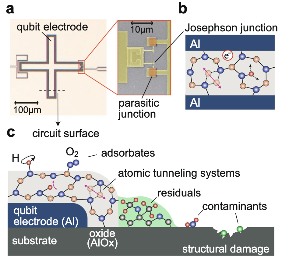
▲ Metal edges, substrate surfaces, oxide tunneling barriers, and packaging structures can all affect and disturb the quantum coherence of superconducting qubits.
b. Schematic illustration of defect types in the amorphous \(AlO_x\) tunneling barrier of a Josephson junction, including atomic-defect two-level systems, or TLSs, in which atoms switch between two potential wells formed by a defect, as well as hydrogen impurities and trapped electrons.
c. Schematic illustration of surface defects, showing a cross-section of the qubit electrode and its native aluminum oxide layer. Structural TLSs may exist inside this oxide layer. In addition, adsorbates such as hydrogen (\(H\)) and oxygen (\(O_2\)) can provide surface spins. Processing residues, such as photoresist, airborne contaminants, and substrate amorphization caused by circuit patterning, are also sources of surface-induced decoherence.
Ref: doi.org/10.1038/s41534-019-0224-1
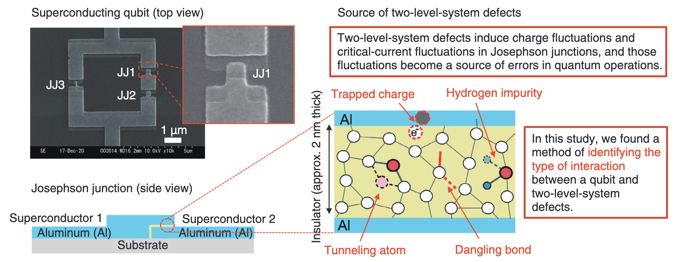
▲ Another schematic study illustrating material-related decoherence sources, including trapped electrons, hydrogen impurities, atomic TLS defects formed by double-well potentials, and unpaired dangling bonds between atoms.
Ref: 10.53829/ntr202411fr1
TLS Defects: A Physical Mechanism Behind Decoherence
Two-level systems, commonly abbreviated as TLSs, are a widely used model for material defects in superconducting qubits. As mentioned above, they may originate from amorphous oxide layers, surface adsorbates, residual contamination, Josephson-junction tunneling barriers, or microscopic structures at metal–substrate interfaces. These defects can be treated as another set of tiny two-level systems. When the energy splitting of a TLS is close to the qubit frequency, the qubit may transfer energy into the TLS, reducing \(T_1\).
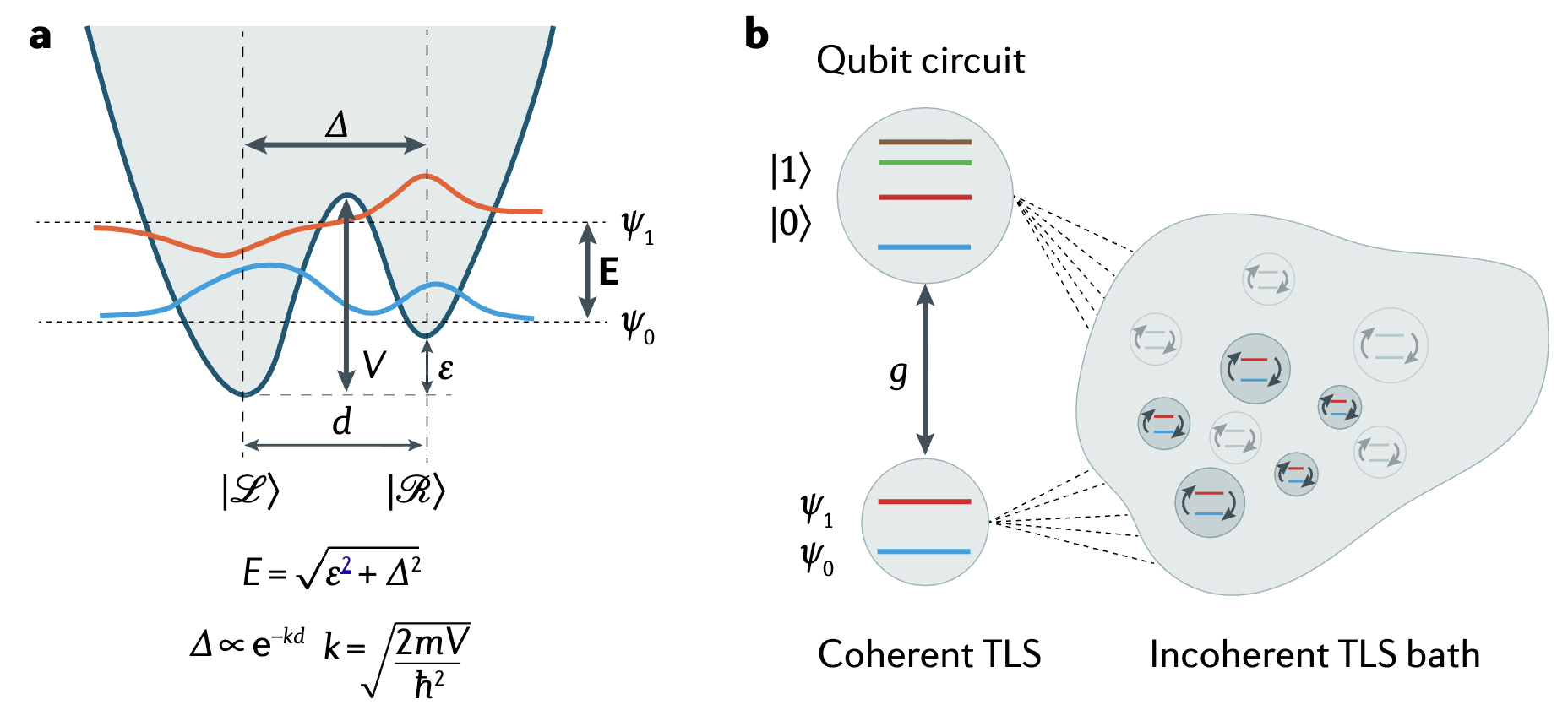
▲ A simple TLS model formed by a double-well potential. In a physical model where the TLS couples directly to the qubit, the coupling strength \(g\) is an important parameter. In addition, many TLSs exist in materials and can indirectly perturb the quantum system; they are often treated as a background field or fluctuating environment.
Ref: 10.1038/s41578-021-00370-4
For tunable qubits, TLS defects can leave identifiable signatures in the spectrum. For example, when the qubit frequency is swept across a TLS, one may observe an avoided crossing, an anomalous Rabi frequency, or an increase in local loss. This is why a superconducting qubit is not only a computational element, but also a sensitive probe of materials. By studying changes in qubit decoherence and spectra, one can infer the presence and coupling properties of defects inside the chip.
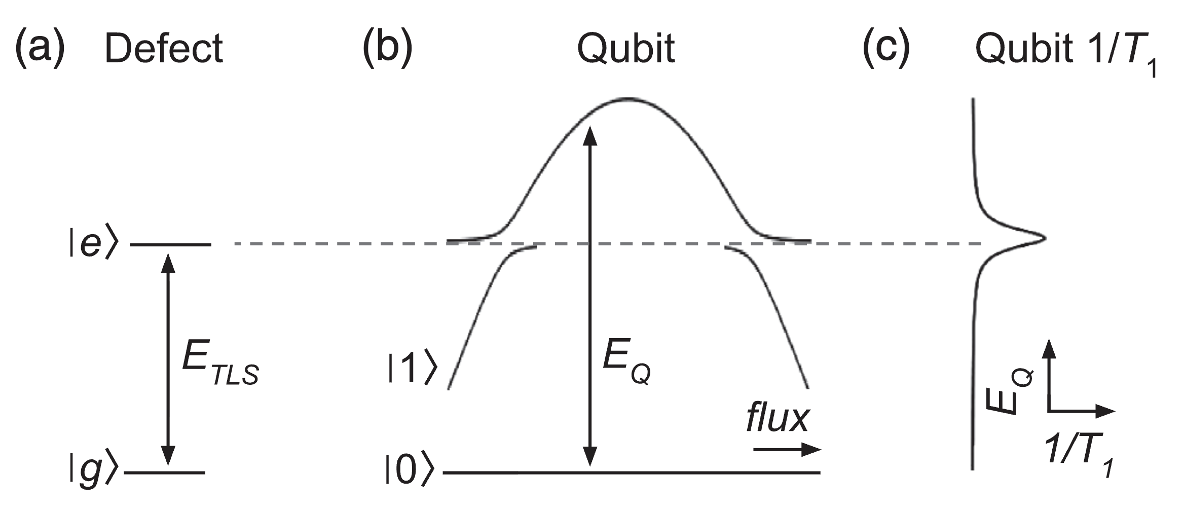
▲ When a qubit is directly coupled to a TLS, tuning the qubit energy level close to the TLS energy level can lead to hybridization between the two quantum states. This phenomenon is known as an avoided crossing. Under this condition, the resonance effect is strong, and a large amount of qubit energy can leak into the TLS, producing energy-relaxation decoherence and reducing \(T_1\).
Ref: 10.1103/PhysRevLett.121.090502
|
|
|---|
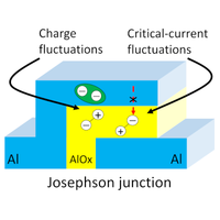
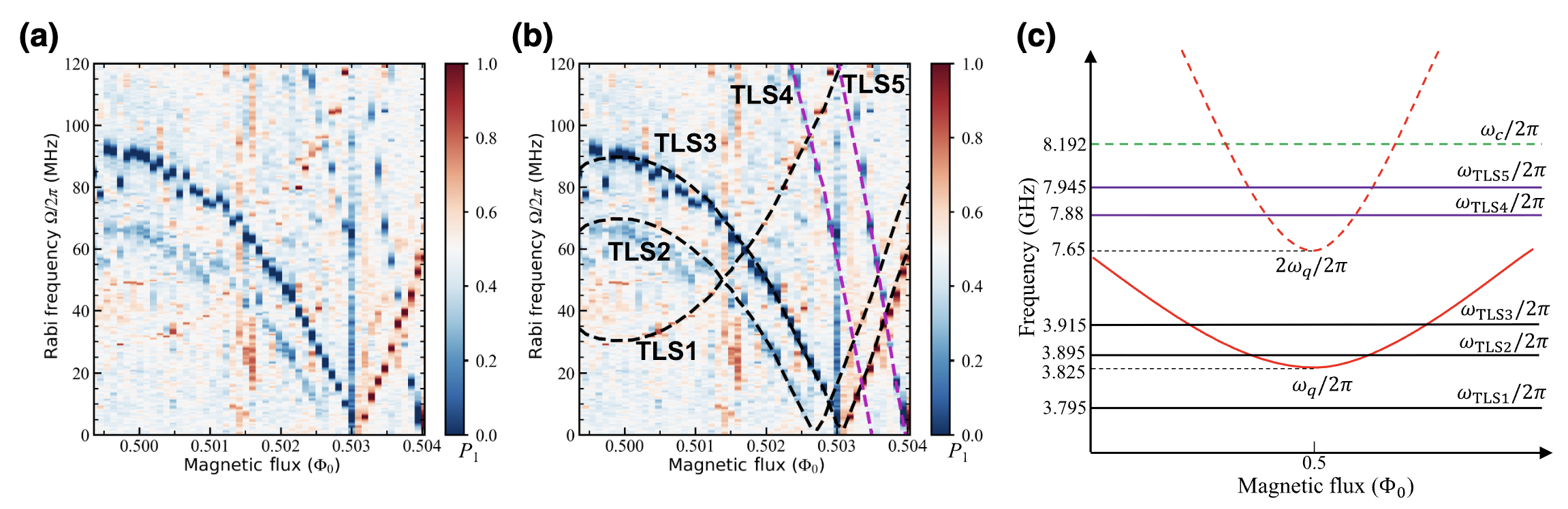
▲ There are many types of TLSs in materials, and different categories of TLSs can be distinguished experimentally. This study discusses two classes of TLS phenomena: electric-field fluctuations, labeled TLS1 to TLS3, and critical-current fluctuations, labeled TLS4 to TLS5.
Ref: 10.1103/PRXQuantum.3.040332
\(T_1\) Drift: The Properties of the Same Qubit Can Change with Frequency and Time
TLS defects do not necessarily remain fixed at the same frequency. They may be influenced by nearby defects, the local charge environment, strain fields, or low-frequency noise, causing their own energy levels to drift. When TLS frequencies drift, the loss environment seen by the qubit also drifts. This provides an important physical picture of decoherence-time drift: the qubit is not drifting alone; the defect environment surrounding the qubit is also slowly changing.
The energy relaxation time \(T_1\) describes the timescale over which a qubit relaxes from the excited state \(\ket{1}\) back to the ground state \(\ket{0}\). A long \(T_1\) means that the qubit can preserve its energy information for a longer time. A shorter \(T_1\), by contrast, increases the probability of errors during gate operations and measurement.
However, \(T_1\) is not a fixed constant. Experiments show that when the qubit frequency is tuned across different spectral regions, a pronounced decrease in \(T_1\) can appear near certain frequencies. This usually indicates that the qubit is close to resonance with local TLS defects, making it easier for energy to flow from the qubit into the defect environment. More importantly, these low-\(T_1\) regions can themselves change over time, producing what is known as decoherence-time drift, or \(T_1\) drift.
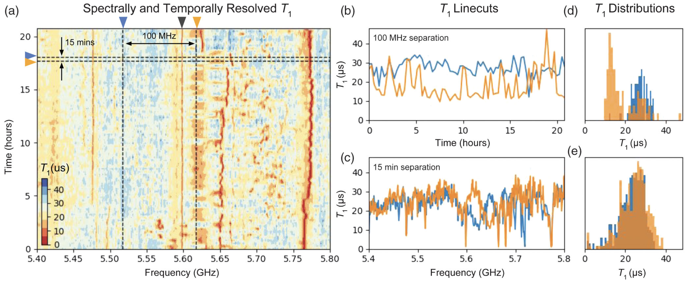
▲ This figure shows \(T_1\) measurements performed across both time and frequency. The horizontal axis corresponds to the tuned qubit frequency, while the vertical axis represents \(T_1\) measured at different times. At a fixed time, sweeping the qubit frequency reveals regions where \(T_1\) is longer, shown in blue, and regions where \(T_1\) is shorter, shown in red. A shorter \(T_1\) indicates strong coupling between the qubit and TLS defects.
As time evolves, the resonance frequencies associated with TLS defects can also shift, as seen from the movement of the red regions. The figure shows that \(T_1\) is nonuniform along both the frequency and time axes. Some frequency regions maintain a low \(T_1\) for an extended period, while others drift, broaden, or suddenly degrade. For a quantum computer, this means that the optimal operating frequency is not permanently fixed. The system may need to avoid newly emerging loss regions or re-estimate error rates during calibration.
Ref: 10.1103/PhysRevLett.121.090502
Originally written in Chinese by the author, these articles are translated into English to invite cross-language resonance.
 Peir-Ru Wang