Superconducting Qubits Under Electron Microscopy
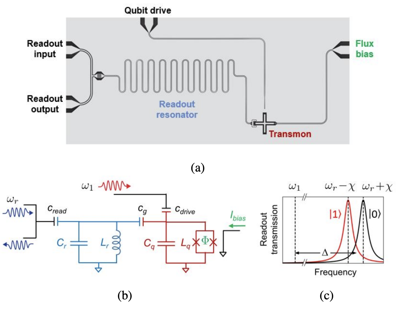
▲ Take a look at the layout of a Transmon. (a) shows the circuit layout under a microscope, and (b) provides the corresponding circuit diagram. In this figure, there is a Qubit (red Transmon), a readout resonator (light blue), and two feedlines, one driving the qubit and the other driving the readout resonator. Components are coupled through capacitors. Additionally, a flux line connected to the Qubit generates a magnetic field to adjust the Transmon's operational frequency. (c) The readout resonator, coupled with the qubit, undergoes frequency shifts depending on whether the qubit is in state \(|0\rangle\) or \(|1\rangle\). This frequency shift characteristic of the readout resonator is used to determine the qubit's state.
arxiv.org/pdf/2106.11352
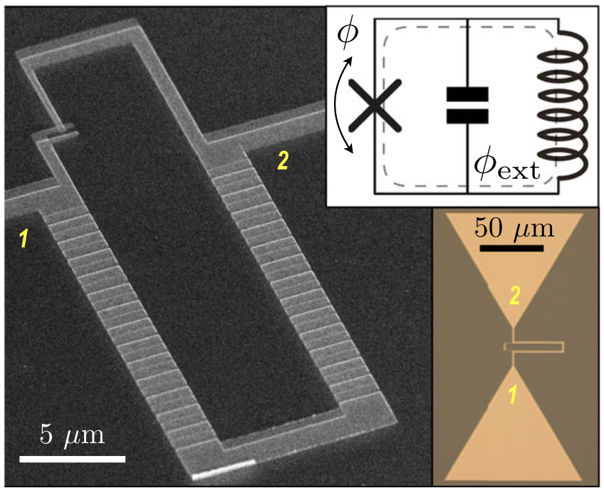
▲ On one side of the Josephson Junction, multiple JJs are connected in series to form an inductor (\(L\)), referred to as Fluxonium.
Ref: 10.1038/s41467-021-26686-x
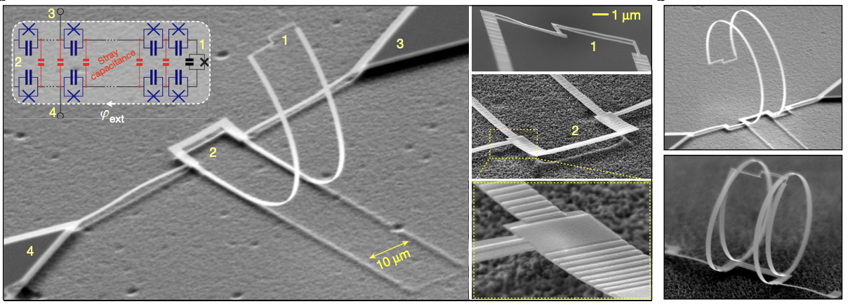
▲ Blochnium can be viewed as an advanced Fluxonium, with its inductor further constructed by connecting more Josephson Junctions in series. Its three-dimensional structure is intriguing.
Ref: 10.1038/s41586-020-2687-9
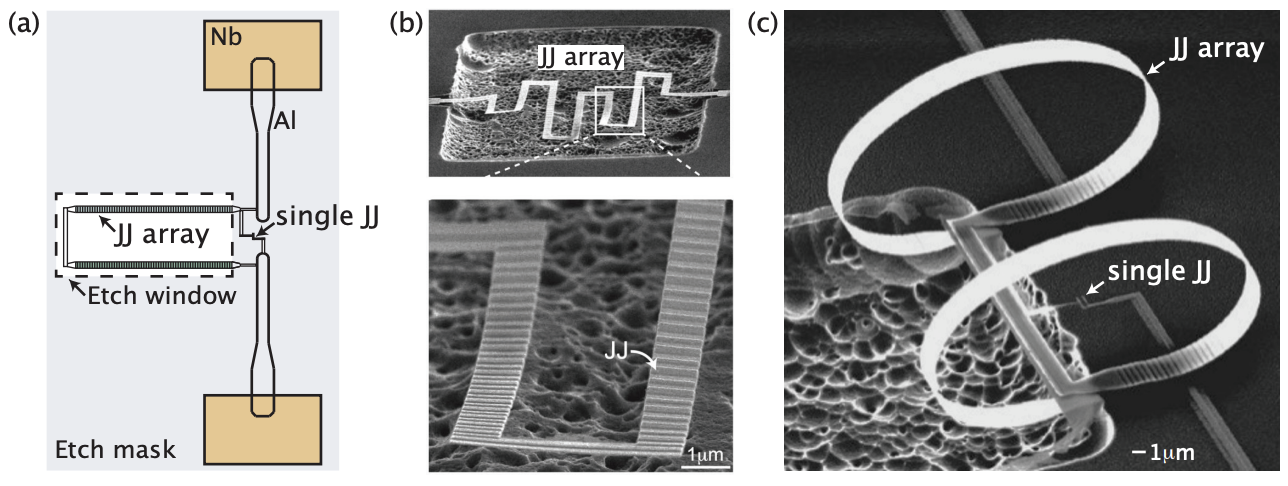
▲ Another image of Josephson Junction arrays in the etching process for Fluxonium/Blochnium. This clearly shows that the squid-like structure is formed by a series of Josephson Junctions.
Ref: arxiv: 2411.10396
This article offers an introductory, popular-science overview for those interested in getting started with superconducting quantum computing. It provides a broad introduction to the principles, types, and key characteristics of superconducting quantum computers. Let’s begin exploring together!
▲
Originally written in Chinese by the author, these articles are translated into English to invite cross-language resonance.
 Peir-Ru Wang