Towards a Scalable QPU - Quantum Chip Design
On the path to quantum computing, integrating thousands or even tens of thousands of qubits is the current direction of effort. However, when multiple superconducting qubits are integrated on a quantum chip, crosstalk between them becomes a severe challenge for quantum computation.
Quantum Computer Development at Academia Sinica
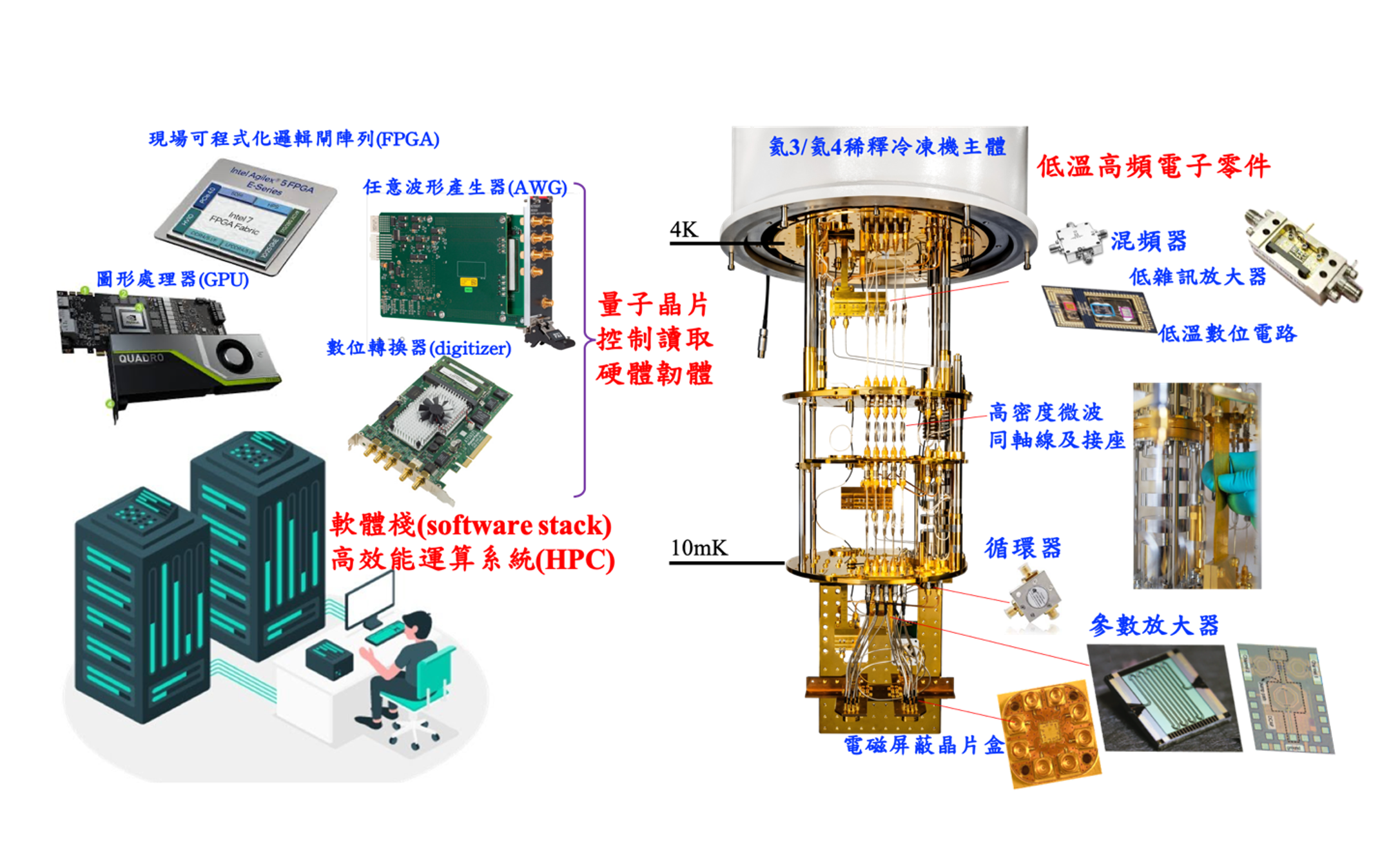
▲ A deconstruction diagram of Academia Sinica's quantum computer. On the left are the external control and analysis hardware, responsible for converting digital signals from classical computers into analog microwave signals to control the superconducting quantum computer, and vice versa. On the right are the relevant microwave components, the quantum chip, and shielding components inside the dilution refrigerator used by Academia Sinica.
Ref: Sinica
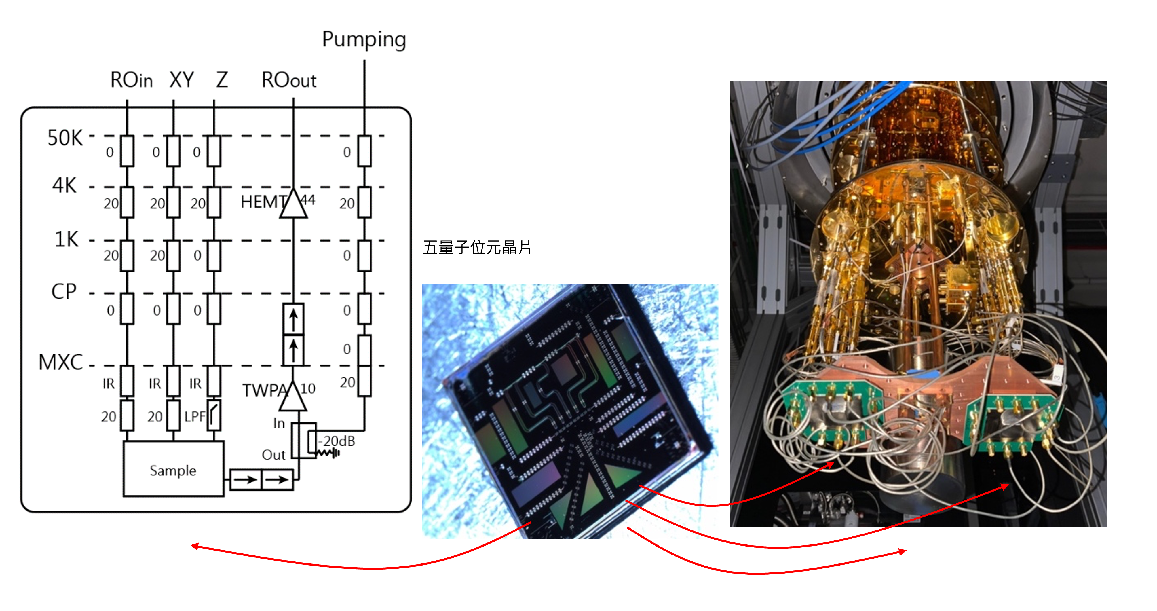
▲ The previous generation 5-qubit chip design from Academia Sinica (it is said a 20-qubit QPU is currently under development).
Ref: Sinica
| I/O Port | Similar Terminology | Functional Description |
|---|---|---|
| XY | Drive line | Used to input control pulses to manipulate the qubit's state (e.g., performing X/Y gates), typically microwave RF signals. |
| Z | Flux line | Provides DC or low-frequency signals to change the effective magnetic flux in a SQUID loop, thereby tuning the frequency of the qubit or resonator. |
| ROin | Readout drive/input | Inputs a microwave pulse to interact with the Readout Resonator. Typically a microwave RF signal. |
| ROout | Readout output | The transmission of the readout resonator changes depending on the qubit's state. The returned signal's amplitude/phase is analyzed by external instruments to determine the qubit state. |
| Pumping | Used to supply the energy needed to excite parametric amplifiers (like JPAs or TWPAs) to boost the signal returning to external instruments, typically providing high-power microwaves at a specific frequency. |
Ref: Sinica
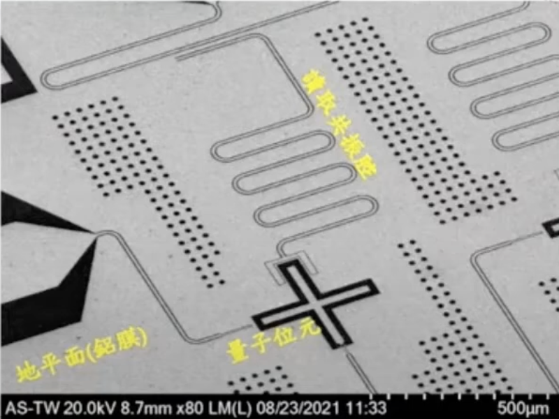
▲ A micrograph of a qubit circuit and a Josephson junction. The design dimensions of the qubit, the length of the resonator, etc., are all part of the design know-how. For example, the natural frequency of a traditional Transmon is around 5-9 GHz, which is determined by two considerations:
- Upper Limit: The superconducting temperature of the material determines the upper limit. Currently, due to the advantages of aluminum in the fabrication process and its excellent yield, most Josephson Junctions (JJs) use an \(Al-Al_2 O_3-Al\) SIS structure (for a related explanation, see "Superconducting Qubits (Advanced): Josephson Junctions"). The critical temperature of aluminum is 1.2K, meaning its superconducting Cooper pair energy gap \( \Delta \) is \( \Delta=1.76 k_B T_c\). From quantum mechanics, the corresponding frequency is about 40 GHz. If the operating frequency approaches or exceeds this, it can cause quasiparticle excitation or destroy superconductivity, leading to decoherence.
- Lower Limit: This is determined by the background temperature of the quantum computer's operation. Current superconducting quantum computers operate at 10-20 mK, corresponding to a thermal excitation frequency of about 400 MHz (calculated at 20mK). If the qubit's operating frequency is close to this thermal noise, it can be easily excited from its ground state, causing errors. The qubit's design frequency must minimize interference from the thermal background, so the ambient temperature determines the lower limit.
Based on these two requirements, the operating frequency for aluminum-based superconducting qubits is set in the 1-10 GHz range. (Of course, for non-superconducting qubits, the operating frequency can be in different ranges. For example, silicon-based spin qubits can operate at 1K, and photonic qubits can operate at room temperature, thus their upper and lower limits differ.) The capacitance energy \(E_C\) of the superconducting qubit is designed according to the operating frequency, and its dimensions and geometry are determined through electromagnetic simulations to achieve the design shown in the figure. The length of the resonator is also determined by its operating frequency.
Problems to Face When Moving Towards Multi-Qubit Systems
To achieve a fundamental quantum advantage, one popular notion is that at least 50 logical qubits are needed. This is based on the idea that the computational space represented by 50 logical qubits is \(2^{50}\) dimensions, and \(2^{50}\approx 1024 TB\), which is enough to represent the data volume of most classical computer calculations. This sounds simple, but in reality, it requires over a thousand physical qubits, which involves the topic of Quantum Error Correction. For example, using the Shor's 9-qubit code, one logical qubit requires 9 physical qubits + 8 ancilla qubits = 17 qubits. Thus, 50 logical qubits would involve at least 850 qubits in the computation process. (Of course, Shor's 9-qubit code is an early, relatively "inefficient" method of error correction, but it was a groundbreaking achievement. In recent years, codes like the Surface code, Color code, and Bacon-Shor code have emerged to increase qubit utilization efficiency.) To design a QPU, the following issues must be considered:
Classical crosstalk
Quantum crosstalk
Signal Input/Output
Simply put, a single superconducting qubit currently requires at least two control lines (one for XY control, one for Z control). Considering the readout lines (one in, one out) and a pump line for amplification, and further hoping for tunable coupling between qubits (one more control line), one roughly needs five times the number of qubits in external RF signal lines, which is astounding.
Connectivity and Layout
Designing a superconducting quantum chip involves considering the type of superconducting qubits used, the form of coupling between them, the requirements of the readout lines, and the arrangement of all components. Here, we discuss the design requirements for a Transmon-based QPU:
On these issues, the two famous camps, IBM and Google, have adopted completely different strategies. IBM has followed a non-tunable route, while Google has adopted an almost fully tunable route. Below, we analyze the reasons for these differing approaches from a circuit design perspective.
- Are the qubits frequency-tunable?
- Qubit Coupling Schemes
- Readout Resonator Frequency Allocation and Coupling to the Bus
- Line Crossovers, Chip Layering, and Packaging

Ref: Drawn by the author
▲ Left: A fixed-frequency Transmon, with one JJ as a nonlinear inductor. Right: A frequency-tunable Transmon, where a SQUID formed by two JJs allows its dynamic inductance to be controlled by an external magnetic field \(\Phi_B\), thereby tuning its frequency.
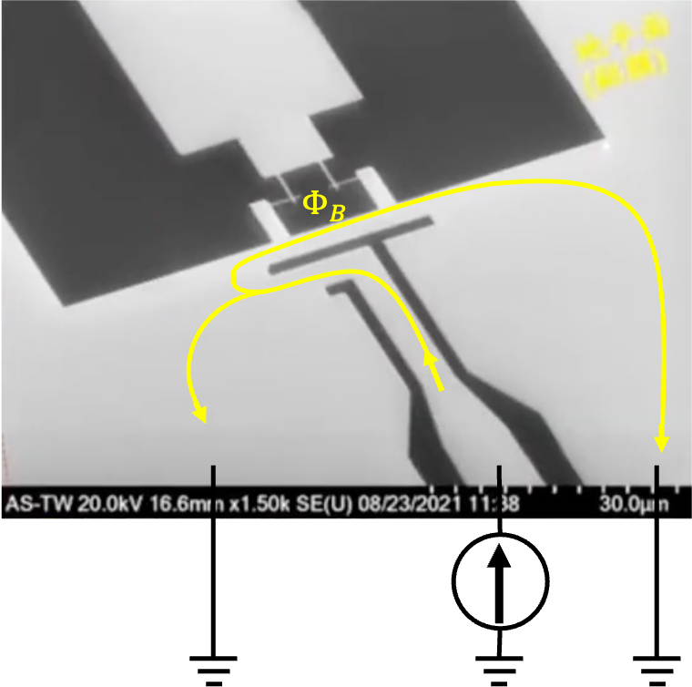
▲ Academia Sinica's Tunable Transmon with a Flux line (Z-Control) under an electron microscope, with a schematic of current flow. By controlling the current magnitude, a magnetic field is generated to tune the Transmon's frequency.
Ref: Modified by the author, original image from "How to Build a Quantum Computer" (Physics Institute, Academia Sinica / Researcher Chi-Dong Chen) https://www.youtube.com/watch?v=wceckog180U&t=3420s
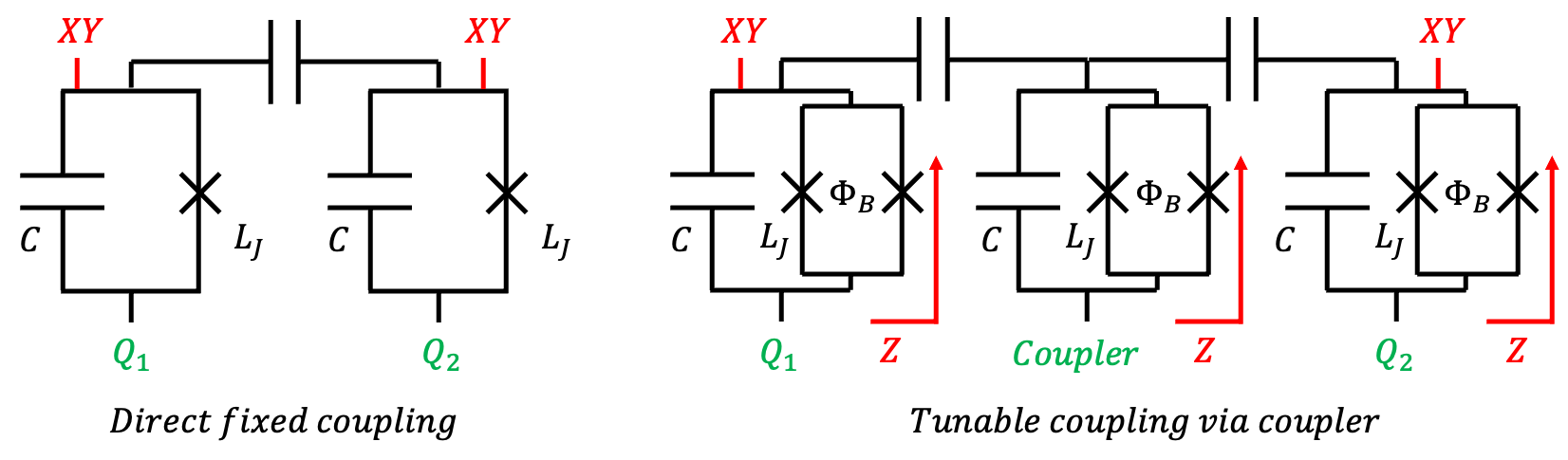
▲ Qubit-qubit coupling schemes. Left is fixed coupling (qubits have fixed frequencies, direct capacitive coupling). Right is fully tunable (qubits have tunable frequencies, coupled via a tunable resonator).
In IBM's fixed design, as shown on the left, each qubit only needs one XY-control line, for a total of two control lines.
In Google's fully tunable design, as on the right, each qubit needs both XY & Z control lines, plus one control line for the tunable resonator, requiring five control lines in total, 2.5 times that of the fixed design.
Ref: Drawn by the author
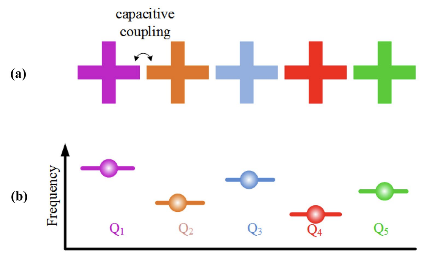
▲ Fixed coupling designs must consider frequency separation between different qubits to avoid unintended crosstalk.
Ref: doi.org/10.1007/s10948-021-06104-5
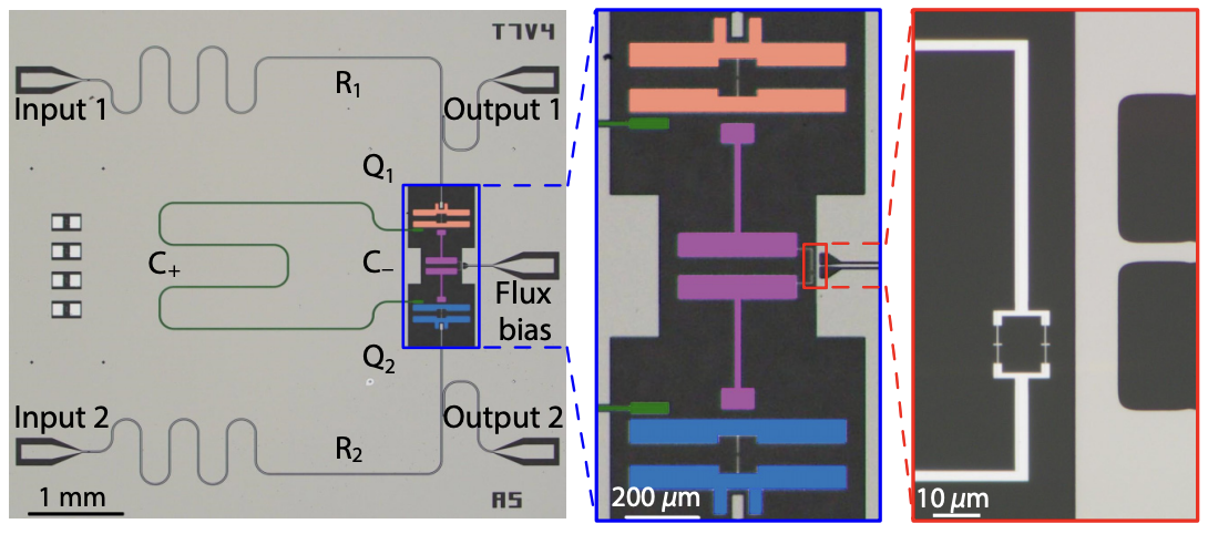
▲ In contrast, tunable designs can control the coupling strength by changing the frequency difference.
When not performing an operation, the coupling resonator's frequency can be set far from the qubits' frequencies. Since coupling strength is inversely proportional to the frequency difference (detuning), the two qubits can be considered isolated.
When a gate operation is needed, the frequency difference is reduced to enable qubit coupling. Tunable designs allow for post-fabrication adjustability, which can correct for fabrication errors and also enable variable QPU topologies, meaning the connectivity between qubits can be changed according to computational needs.
Ref: Suppression of Qubit Crosstalk in a Tunable Coupling Superconducting Circuit
DOI: 10.1103/PhysRevApplied.12.054023
IBM's non-tunable approach can greatly simplify the complexity of circuit design, making it easier to increase fabrication yield. At the same time, fewer external lines mean less incoming noise. IBM believes this approach allows for a faster path to achieving quantum advantage. However, it is forced to face the issues of crosstalk from direct coupling and the complete lack of post-fabrication adjustability.
Google's almost fully tunable approach must confront complex wiring design, more noise interference, and the need for extensive parameter calibration due to the many control parameters. However, because the fully tunable route offers high flexibility, various parameters can be corrected with external instruments to gradually approach optimization. Currently (in 2025), Google is leading, most vendors are adopting tunable designs, and even IBM is slowly moving towards tunability.
.png)
▲ Is it possible to have multiple qubits share the same coupling resonator? There is related research on this. Here, 10 qubits are shown sharing a single coupler (B, Quantum Bus), achieving a form of all-to-all connectivity. A feasible operation could be to park the coupler's frequency far from the qubits'. When two specific qubits need to interact, their frequencies are moved close to the coupler's frequency. After the operation, their frequencies are moved away again.
10-Qubit Entanglement and Parallel Logic Operations with a Superconducting Circuit
DOI: 10.1103/PhysRevLett.119.180511
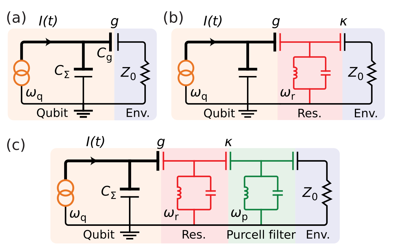
▲ A simplified understanding of qubit readout.
(a) In early days, direct readout was used, where external circuits directly measured the qubit. This easily introduced unwanted noise and was a destructive measurement.
(b) Coupling the qubit to a resonator allows for indirect measurement of the qubit's state by measuring changes in the resonator's frequency, which is a QND measurement that allows for repeated measurements to increase fidelity.
(c) Further pairing with a Purcell filter increases fidelity. The function of the Purcell filter is explained in the next figure.
To learn more about superconducting qubit readout, refer to Superconducting Qubits (Advanced): Quantum Computing Hardware Basics
Ref: A quantum engineer's guide to superconducting qubits
DOI: 10.1063/1.5089550
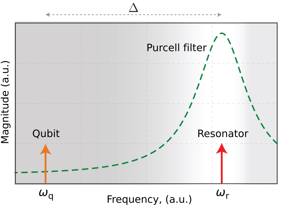
▲ Design consideration for a Purcell Filter's transmission versus frequency. Although pairing a qubit with a coupling resonator can increase measurement fidelity, the qubit's state can still leak out through the resonator, causing decoherence. The Purcell filter's transmission is designed to align with the resonator's frequency, ensuring good input and output of the readout signal, while being suppressed at the qubit's natural frequency. This ensures the qubit's energy cannot leak out, thus enhancing its coherence time.
Ref: A quantum engineer's guide to superconducting qubits
DOI: 10.1063/1.5089550
Currently, in quantum chip design, it is common for individual qubits' readouts to share a single readout line (Readout Bus or feedline). As long as each readout resonator's frequency is distinct, the data can be effectively analyzed through frequency multiplexing. Below are two examples:
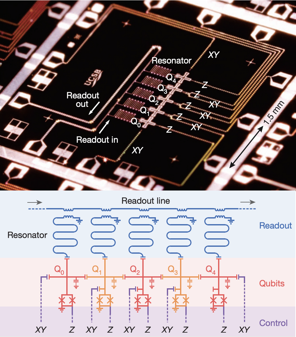
▲ This is a schematic of a 5-qubit layout. Z is the flux line, XY is the drive line, and the 5 qubits are directly capacitively coupled. Additionally, each qubit has its own readout resonator, which is coupled (inductively in this diagram) to the readout line at the top.
Ref: doi.org/10.1038/nature13171
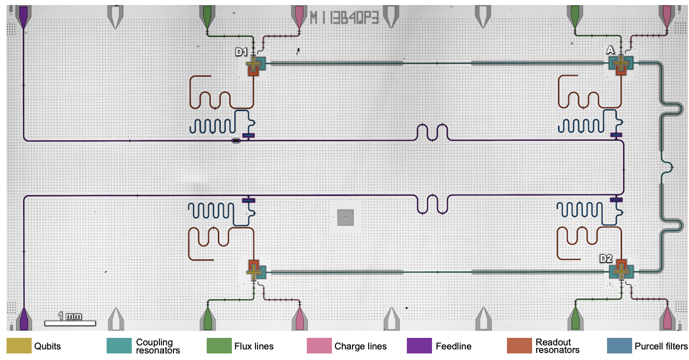
▲ This is also a 5-qubit layout schematic. The "charge line" represents XY control, and the qubits are coupled via fixed-frequency coupling resonators. Comparing this to the previous diagram, you can see a Purcell filter between the readout resonator and the bus line.
Entanglement stabilization using ancilla-based parity detection and real-time feedback in superconducting circuits
DOI: 10.1038/s41534-019-0185-4
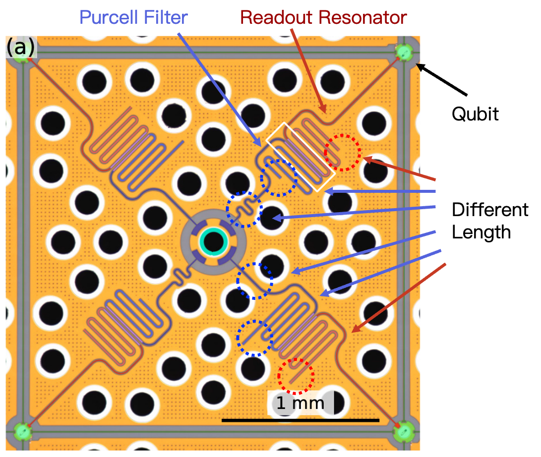
▲This is a 4-qubit layout. At the center of the image is the input of the readout bus, which connects to four Purcell filters and readout resonators. The lengths of the four Purcell filters and readout resonators are all different, indicating that they operate at different frequencies.
Fast Multiplexed Superconducting-Qubit Readout with Intrinsic Purcell Filtering Using a Multiconductor Transmission Line
DOI: 10.1103/PRXQuantum.6.020345
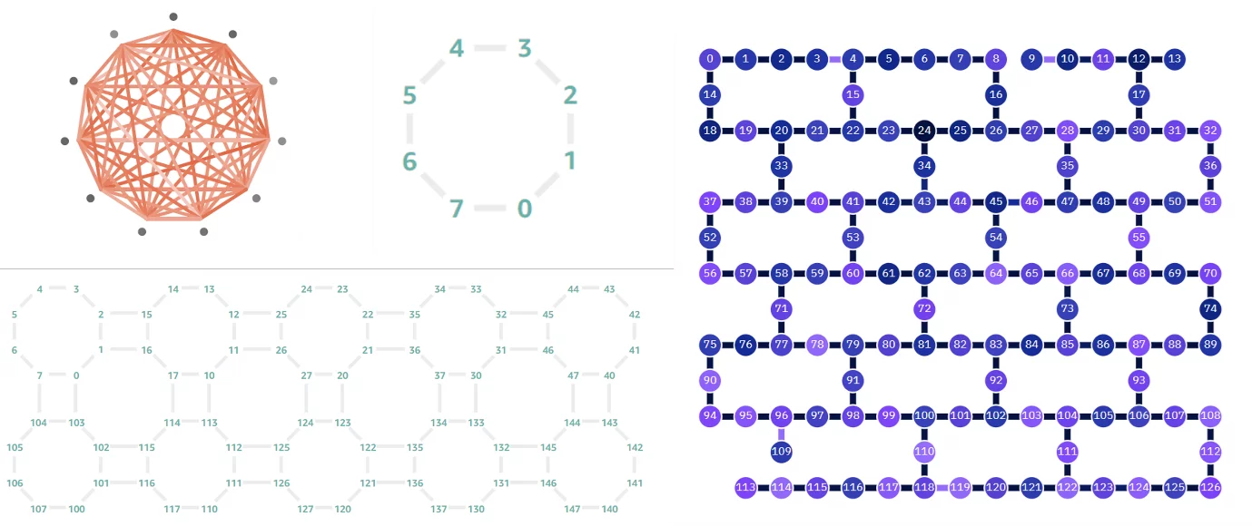
▲ QPU topology represents the connectivity between qubits. To achieve a quantum algorithmic advantage, implementing all-to-all connectivity between qubits is an important goal. However, for solid-state qubit systems (like superconducting or semiconductor qubits), they are mostly arranged in a planar fashion due to fabrication constraints. This means that without 3D wiring, a qubit can only couple to its nearest neighbors. The figure on the right shows IBM's current QPU topology. In contrast, for non-solid-state systems like ion trap quantum computers, remote coupling can be achieved through the dipole-dipole interaction of ions, thus realizing all-to-all connectivity.
Ref: https://thequantuminsider.com/2022/08/12/a-guide-to-quantum-computing-benchmarking-and-certification/
Schematic representation of different QPU topologies. (Top-left: IonQ, Top-center: OXC, Bottom-left: Rigetti, Right: IBM). Images compiled from AWS Braket and IBM Quantum Experience sites.
▲ Firstly, since solid-state qubit systems are mostly planar, the complex routing of various control lines inevitably leads to crossover issues. This requires careful design for crossovers between components (e.g., a control line can cross over a resonator/coupler, but not vice versa) or to avoid crossovers entirely (no line can cross over a qubit).
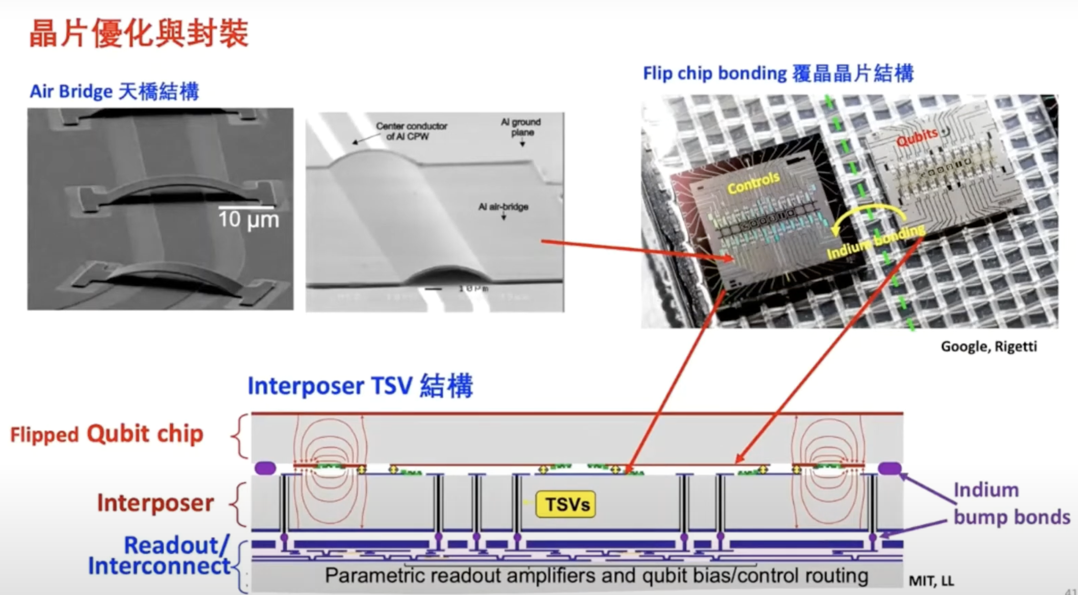
Secondly, quantum chips also require significant effort in packaging. Currently, flip-chip packaging is mainly used. To maintain qubit fidelity from interference from other components, the chip can be split into two layers: the high-quality region for the qubits, and another layer for control lines, readout lines, etc., which are then stacked together.
Ref: How to Build a Quantum Computer (Physics Institute, Academia Sinica / Researcher Chi-Dong Chen) https://www.youtube.com/watch?v=wceckog180U&t=3420s
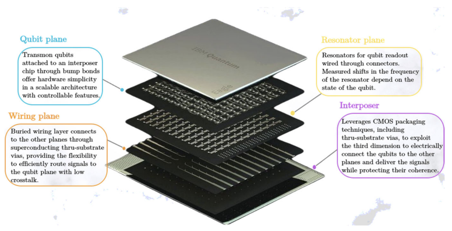
▲ In addition to two-layer stacking, there is a trend towards distributing different functional components onto separate chip layers. The figure shows IBM Eagle's design, which separates qubits, control lines, and resonators onto different chip layers to reduce interference.
Ref: IBM quantum computers: evolution, performance, and future directions
DOI: 10.1007/s11227-025-07047-7
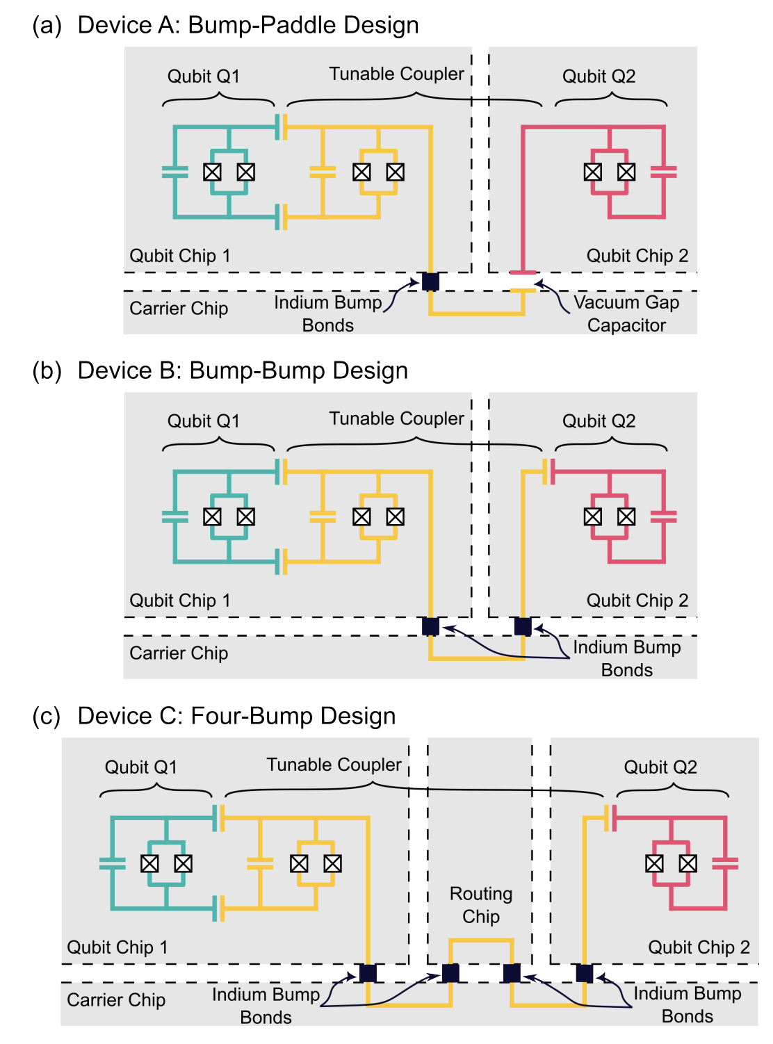
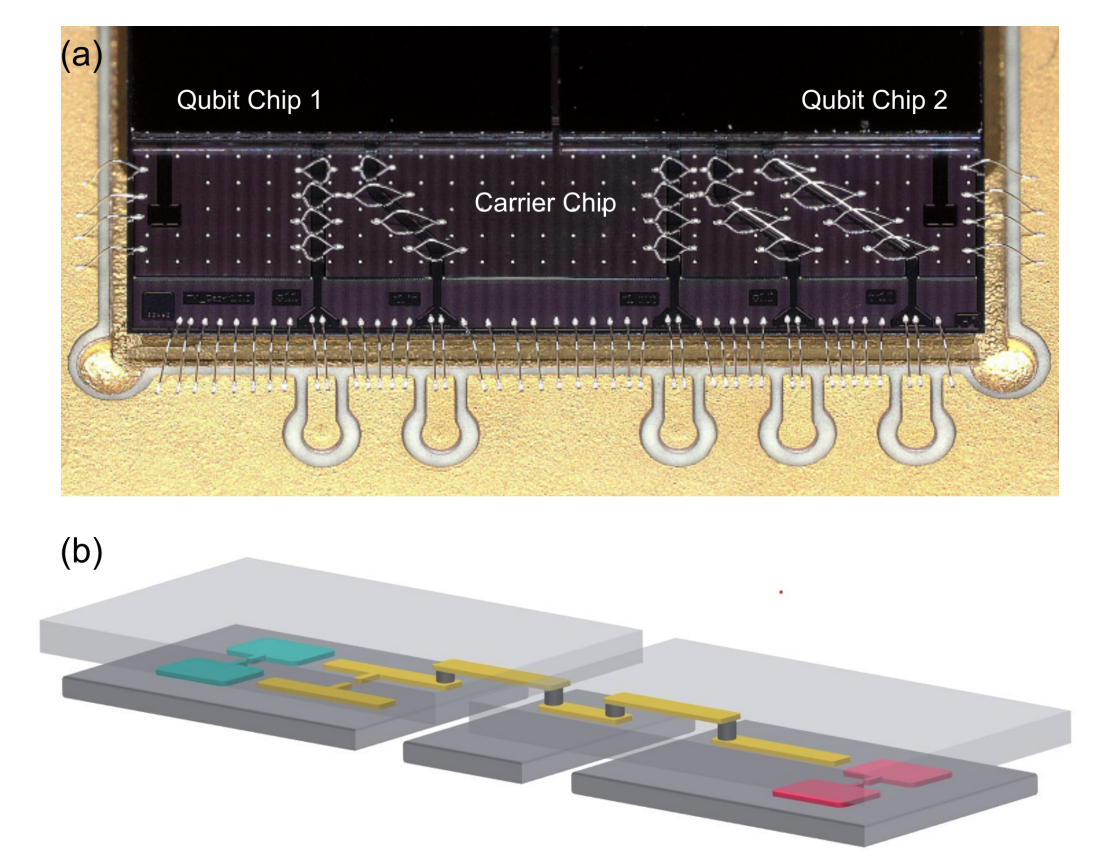
▲ Due to fabrication constraints and the non-trivial size of superconducting qubits, it is difficult to fit a large number of qubits on a single chip. Therefore, achieving inter-chip coupling between superconducting qubits while maintaining their quantum properties is a significant experimental and packaging challenge.
Modular superconducting-qubit architecture with a multichip tunable coupler
DOI: 10.1103/PhysRevApplied.21.054063
The Issue of Crosstalk: Classical and Quantum
In the current stage of quantum computer development, the system is strictly a semi-classical, semi-quantum hybrid. Classical computers send microwave signals carrying classical information, which interact with the qubits. The qubits then return classical signals carrying quantum information, which are analyzed by the classical computer.
This characteristic allows us to roughly categorize crosstalk into classical and quantum crosstalk.
Unintended effects caused by control signals and gate operations are classified as classical crosstalk. Quantum crosstalk, on the other hand, arises when the state of other qubits causes the control of a specific target qubit to be less precise than expected. This will be discussed in the next section.
|
This article is based on a talk given by Prof. Watson Kuo from National Chung Hsing University, at the invitation of Prof. Li-Yi Hsu from Chung Yuan Christian University, on the topic of:
Key issues in designing a scalable QPU
Event Date: 2025-06-18 Speaker: Prof. Watson Kuo (Dept. of Physics, National Chung Hsing University) Host: Prof. Li-Yi Hsu (CYCU) Place: R211, Science Building, Chung Yuan Christian University Time: 14:00 The author was deeply inspired and expresses sincere gratitude. |
|---|
Originally written in Chinese by the author, these articles are translated into English to invite cross-language resonance.
 Peir-Ru Wang